
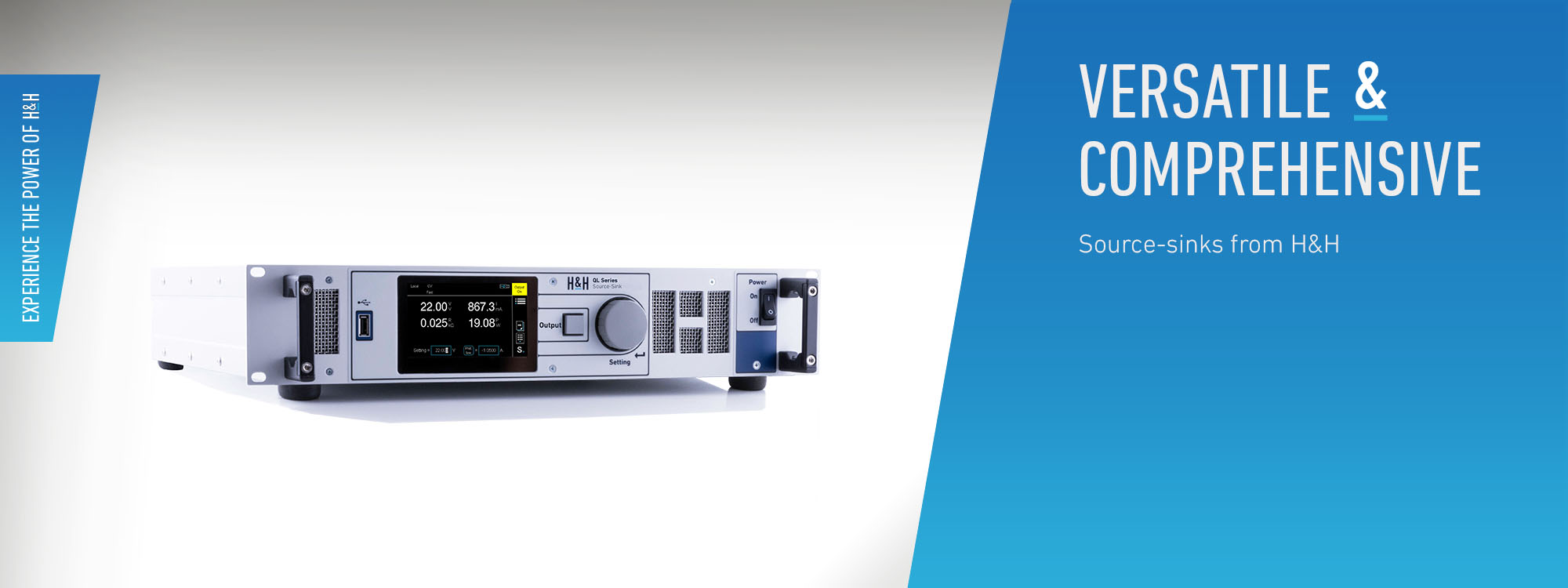
QL Series - Source-Sink
Features of performance
Details
Model overview
Downloads
- Voltage up to 100 V
- Currents up to 320 A
- 2-quadrant or 4-quadrant design
- DC source-sink
- Additional AC source for 4-quadrant models
- User interface with 4.3" touch screen
- Basic operating modes CC, CV, CP, CR
- Combined operating modes CC+CV, CV+CC
- Adjustable upper and lower limits for V and I
- Adjustable internal resistance in CC and CV modes
- Capacitance simulation
- Internal resistance measurement
- List function with synchronous data acquisition
- Rectangular, PWM and modulation function
- Trigger model
- SCPI programming with measurement functions
- RS-232, USB, LAN, CAN, I/O port standard
- GPIB optional
- Isolated I/O port optional
- Analog monitoring outputs for voltage and current
- Analog control inputs for control V/I and limit V/I
- Save settings
- Electronic protection
- Bilingual help system (DE, EN)
- 2 free calibrations (with registration)
Description
QL series devices are sources and sinks or power supply and electronic load in one device. They are used for testing a wide variety of energy storage devices, as well as other DUTs such as motors, chargers or coils.Operating Modes
Basic Operating Modes
The devices have constant current (CC), constant voltage (CV), constant resistance (CR) and constant power (CP) operating modes.Combined Operating Modes
In CV mode, two current limits (source and sink current) can be set independently. In CC mode, an upper and a lower limit voltage can be set. This provides the combined operating modes CC+CV and CV+CC.AC Source
4-quadrant devices are also capable of the AC source operating mode.Source-Sink Mode
Depending on the output variable setting and the characteristics of the connected DUT, the instrument automatically decides whether to operate as a source or a sink.2- or 4-Quadrant Models
Instruments for 2-quadrant operation can supply or sink current when the output voltage is positive. To ensure that the desired function is provided at settings close to 0 V and with longer leads, 2-quadrant devices operate at negative voltages starting at -1 V. So in principle, 2-quadrant devices are also 4-quadrant devices, but with limited negative voltage. 4-quadrant devices can also be used as AC sources.Functions
Internal Resistance Measurement
In sink mode, the device can measure the DC internal resistance of the connected source. For this purpose, it uses a calculation method specified in various standards, e.g. DIN EN 61951, DIN EN 61960.Adjustable Internal Resistance
In order to simulate different sources as flexibly as possible, a variable internal resistance can be set in constant voltage mode CV. Similarly, a conductance can be set in constant current mode CC.Capacitance Simulation
The capacitance simulation function is used to simulate energy storage devices such as capacitors, batteries, accumulators, etc.. In addition to the capacity to be simulated, the start voltage is also to be defined.List Function
Dynamic processes (LIST function) can be simulated with up to 300 set values. The setpoint lists may contain positive and negative values across quadrants, so that there are, for example, charging and discharging currents in one list. The device stores the synchronously acquired measurement values with time stamp.Rectangular Function
The rectangular function provides a convenient way to generate a square waveform by entering absolute times and current or voltage values.PWM Function
With the PWM function, the frequency and the duty cycle can be set in manual mode for the two current or voltage values.Modulator
In CC- or CV- mode the modulator adds a sinusoidal, rectangular, triangular or arbitrary signal to a constant setpoint. Frequency and modulation depth are adjustable.AC Source
4-quadrant devices can be used as DC source-sink in the basic modes CC, CV, CP and CR and additionally as AC source in the modes CC and CV. Selectable waveforms are sine, triangle, square, sawtooth or an arbitrary waveform, with adjustable offset. For measurements without oscillations, the waveform can be synchronized in frequency and phase with the mains voltage.Measurement Data Acquisition
Automatic data acquisition allows measurement data to be stored internally or directly to an external USB flash drive.Trigger Model
Various functions or settings can be triggered by a configurable trigger event:- Switch source output on/off
- Set triggered operating mode
- Start/stop list operation
- Start/stop data acquisition
- Set triggered settings of all operating modes
- External
- Bus
- Manual
- Voltage
- Current
Control Speed Selection
For certain DUTs or very long cables, it may be necessary to adjust the regulation time constant of the source-sink to avoid oscillation and to achieve stable operation. The control speed can be selected from slow - fast.Watchdog Function
When the watchdog function is activated, the output is switched off in the event of faulty communication with the control PC in order to protect the connected DUT.Saving Settings
In order to be able to quickly reconstruct recurring test tasks, the active settings can be stored in non-volatile memory (internally or on USB flash drive) so that they can be reloaded at a later time. 9 internal memory positions are available. The unit can selectively set reset values at power-up, the last active settings at power-down, or memory positions 1 to 9.Data Interfaces
The following data interfaces are fitted as standard:- Ethernet
- USB
- RS-232
- CAN
- GPIB Interface (option QL02)
I/O Port
The standard I/O port provides analog and digital signals for external control. Inputs:- Analog setting of I and V with -5 ... 0 ... 5 V or with -10 ... 0 ... 10 V
- Analog upper and lower limit value setting of I or V with -10 ... 0 ... 10 V
- Output switching
- Selection of operating mode CC/CV
- Control speed selection
- Remote shut-down
- Readable digital input
- Trigger input
- Analog voltage monitoring output -10 ... 0 ... 10 V
- Analog current monitoring output -10 ... 0 ... 10 V
- Output activation status
- Status output for upper limit value
- Status output for lower limit value
- Trigger output
Galvanically Isolated I/O Port
For galvanic isolation of the I/O port from the output circuit and thus to prevent ground loops, the option QL06 can be installed. The galvanically isolated version is pin compatible to the standard version.Help System
The integrated help system supports the user in the manual operation of the devices. The language can be switched between German and English.Calibration
A free Factory Calibration Certificate (FCC) is supplied with the devices. The calibration process is subject to supervision in accordance with DIN EN ISO 9001. The calibration certificate documents the traceability to national standards to illustrate the physical device in accordance with the international System of Units (SI). Within the 2-year warranty period, we will calibrate a second time free of charge if the respective device (serial number) will have been registrated at H&H.--> Conditions for a second free calibration
For use under laboratory conditions, H&H recommends a calibration interval of 2 years. This is an empirical value that can be used as a guide for the first period of use. Depending on the intended use, service life, relevance of the application and ambient conditions, the operator should adjust this interval accordingly.Documentation
We supply a user manual as pdf file and printed General Safety Instructions, each in German and English.Manuals
Software/Drivers
QL_Tool_1.0.0.zip
Software tool for control of QL series source-sinks with firmware revision up from 1.1.0
Software tool for control of QL series source-sinks with firmware revision up from 1.1.0