

Basics
What is an electronic load?
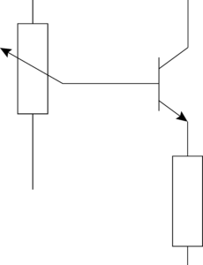
An electronic load is the counterpart of a current source, i.e. a current sink. It is a device originally used as an intelligent replacement for a conventional (resistive) load resistor. Today, an electronic load replicates all imaginable types of loads.
Whereas when loading a voltage source with a fixed resistor, one always sets a specific load current with a single resistor value. The special feature of the electronic load is that it can vary the load current within a defined range. It regulates the current electronically by means of transistors.
Customers use electronic loads in a wide variety of applications, especially for testing power supply and control units, batteries, fuel and solar cells, generators, transformers, uninterruptible power supplies (UPS), on-board power systems and many more.
In addition, H&H electronic loads have a considerable range of functions, which ensure convenient use. With functions such as MPP tracking, discharge function or internal resistance measurement, the devices perform complex processes for measurement and data storage automatically.
Analog and digital interfaces are essential for automated test stands, which electronic loads from Höcherl & Hackl usually provide as standard.
What are electronic DC loads used for?
H&H electronic DC loads are used in the automotive, aerospace, railroad, renewable energy, R&D, medical and military industries. DC loads are used to test the following components:
Power supplies, laboratory power supplies
Static or dynamic loading in various modes, burn-in test. To determine the V/I characteristics of power supplies from open circuit to short circuit, one also needs electronic loads that can regulate high load currents at input voltages close to 0V. For this purpose there are special models of DC loads: PLI ZV series.
Control units
When testing control units, simultaneous loading of several different units is often required by simulating different loads, e.g. in a car. We serve such applications with our modular multi-channel load series PMLA, effectively many electronic DC loads in one housing.
Power distribution, cable trees, fuse boxes
Here, too, many different loads are simulated by several channels of a PMLA multi-channel load.
Batteries and accumulators
Energy storage devices are discharged continuously or with defined load profiles to assess their quality. With the discharge function this is done professionally including protection functions and individual shutdown criteria. To cycle accumulators, devices for charging and discharging are necessary. For this purpose, either a power supply can be added to the system in addition to the electronic load, or a source-sink from H&H, which switches seamlessly between charging and discharging mode. The source-sink is available as a 2- or 4-quadrant power supply.
Fuel cells
The PLI ZV zero-volt models are also used for testing fuel cells, because here one has to deal with voltages far below 1 V at high currents. Impedance spectroscopy is used to examine fuel cells in order to determine, for example, the series resistance or the end of life (EOL). The SCL series is designed even more for high currents down to 0 V.
Solar and photovoltaic panels
For PV panels, the maximum power point (MPP) plays a key role. Our DC loads offer the MPP tracking function either standard or optional, depending on the series. For applications with high demands on the accuracy of current control over wide ranges, we have models with several adjustable current setting ranges in our portfolio: series PLI MR.
Testing and simulating components
such as diodes, rectifiers, fuses …
Testing of continuous, short-time or pulsed current capability of active and passive components. With the V/I-characteristic function of the PLA series, the characteristic curve of a component is reproduced in the electronic load. For this purpose, the load sets the corresponding load current depending on the applied input voltage.
What are electronic AC loads used for?
Electronic AC loads are used in these areas:
- Testing AC power supplies
- Testing transformers
- Testing inverters
- Testing uninterruptible power supplies (UPS)
- Testing aircraft electrical systems
- Testing generators
- Burn-in test
- Testing smart grids, micro grids / stand-alone grids
- Testing chargers, charging stations, wallboxes
- Testing energy meters
- Testing emergency generators
- Testing according to standards, safety tests
For testing three-phase power supplies, there are the three-phase loads of the ACLT series.
What do CC, CR, CP, CV mean?
CC, CP, CR, CV are the 4 basic operating modes of almost every H&H electronic load:
- Constant current (CC) operation: Independent of the applied input voltage, the load controls a constant current flow with the current setting value.
- Constant power operation (CP): Depending on the input voltage, the load regulates the current flow so that the power set remains constant.
- Constant resistance (CR) operation: Depending on the input voltage, the load regulates the current flow so that the set resistance remains constant.
- Constant voltage (CV) operation: In voltage mode, the load regulates the input voltage to the specified set point. This is done by adjusting the load current until the desired voltage is established by the DUT’s internal resistance or current limit.
QL series source sinks also have these 4 basic modes of operation.
What are combined operating modes?
Combined operating modes are characterized as the interaction of basic operating mode (CC, CR, CP, CV) and adjustable overcurrent or undervoltage protection.
The following combined operating modes are available, depending on whether only one of the limitations is active or both simultaneously:
- CC+CV Constant current operation with undervoltage protection
- CR+CC Constant resistance operation with overcurrent protection
- CR+CV constant resistance operation with undervoltage protection
- CR+CC+CV Constant resistance operation with overcurrent and undervoltage protection
- CP+CC Constant power operation with overcurrent protection
- CP+CV Constant power operation with undervoltage protection
- CP+CC+CV Constant power operation with overcurrent and undervoltage protection
- CV+CC Constant voltage operation with overcurrent protection
What is the meaning of the minimum input voltage?
The minimum input voltage is necessary at the load input in order to absorb the maximum load current Imax. We specify this minimum input voltage Vmin for each device model in the technical data. The electronic load can regulate lower currents than Imax even at voltages below Vmin.
What is a source-sink?
We use the term source-sink for 4-quadrant power supplies – these are devices that allow both current and voltages in both positive and negative directions.
A 2-quadrant power supply is also a source-sink. Another term for these devices is bi-directional power supply because current can flow both out of the device (source) and into the device (sink). The QL series offers 2- and 4-quadrant models in a wide range of power and with many features.
Why shall I connect the sense lines?
The sense lines are used to compensate for voltage drops on the load lines.
The longer the load lines and thus the greater the ohmic resistance of the load lines, the higher the voltage drop on them. The greater the difference between the voltage at the output of the device under test (DUT) and the voltage at the load input, the less accurate the control response of the load. To compensate for the voltage drop, connect the sense lines separately and apart from the load lines directly to the DUT output:
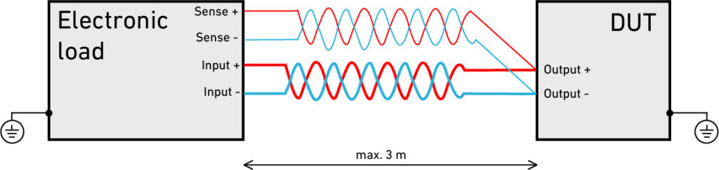
Input and sense lines
If the sense connections are not wired, the load will automatically measure the voltage at the load input. However, the accuracies for voltage measurement given in the technical data only apply when sense lines are connected.
Prevention and Troubleshooting
How do ground loops occur and how can I prevent them?
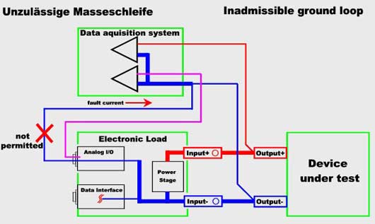
Ground Loops can be prevented by using galvanically isolated analog inputs at the data acquisition system or electronic load. For this case we can offer a “galvanically isolated analog I/O port for many series”. The standard analog I/O card can be exchanged by an insulated version. All measuring and controlling signals are connected via insulating amplifiers and optocouplers.
What are the effects of the electronic load’s input capacity?
Each electronic load has a certain input capacity (see technical data). This is hardly noticeable with clean DC input voltages.
However, if the voltage at the load input is superimposed with an AC voltage component, the load current also contains an AC current component depending on the amplitude and frequency of the AC voltage. This is not an oscillation of the electronic load.
If the amplitude portion or the frequency of the AC voltage component is high, an overload of the input capacity can occur!
The accuracy values given in the technical data apply for clean DC voltages at the load input.
How can I avoid distorted analog outputs?
Especially when clocked power supplies are tested, situations may occur in which the monitor outputs for current, voltage etc. at the analog I/O connector are distorted.
The causation has to be searched in the way of test assembly.
Clocked power supplies have got filters in the output circuit and capacitors from the output to protective earth.
Also the electronic load and other instruments include filters because of EMV reasons.
The common mode noise voltage (voltage between each output terminal and protective earth) causes a differential current through the anti-interference capacitor and the electronic load (or other instruments) back to the load output.
This differential current often generates high-frequent superpositions at the measurement signals.
At dynamic tests very high interference voltage may occur.
To solve this problem, you can supply the electronic load and/or the other instruments by insulating transformers with low coupling capacity.
Thereby the interference circuit is interrupted and the measurement quality is increased.
How can I measure the current slew rate?
The current slew rate measurement must be donewith a clip-on probe which is fast enough. (E.g. Tektronix Current Measurement )
Current measurements by measurement shunts mostly deliver faulty results since most shunts are inductive. Such measurements deliver false slew rates with oscillations.
How can I prevent a distorted slew rate in dynamic mode?
To reach the best possible current slew rate in dynamic mode the following conditions have to be fulfilled:
- The dynamic input resistance of the voltage supply has to be very low. The electronic load is not able to compensate voltage variations at the moment of the fastest possible current variation.
- The resistance of the input lines must be very low (same reason as in a) )
- The input lines must be non-inductive. Inductive lines (all cables have got an inductive component) in addition with its ohmic resistance result in a limitation of the maximum possible current slew rate. The electronic load can not perform a fast current slew rate if the slew rate is limited by the connecting lines. Furthermore, the connecting lines behave like an energy store (self-induction) and deliver current into load and UUT when being unloaded.
How can I avoid input coupling by current drawing lines?
Especially in Constant Resistance mode you have to note that an input coupling from the input lines to the voltage measurement may occur if sense lines are used.
Since in constant resistance mode the exact acquisition of the input voltage is important to make the correct current setting a magnetic coupling into the sense lines causing a positive feedback makes the system instable.
At first, you have to reduce the coupling.
That means:
Separate the sense lines from the input lines. Also separate the sense lines from all other lines drawing current, e.g. mains supply.
The sense lines should be twisted to eliminate the induced voltage.
Never twist the sense lines with any of the current drawing lines!
The load input lines should be twisted or at least run in parallel to compensate the magnetic fields.
And of course:
Keep all lines as short as possible!
If all these steps don’t bring the desired success, a capacitor may be connected between the sense lines.
How can I prevent stability problems caused by an oscillating system?
When power supplies or other circuit arrangements stabilizing an output parameter by a control loop are tested, two regulators are connected together when applying the electronic load to the UUT. When a phase shift of more than 180° and an amplification >1 are reached by the system, the oscillation condition is true and the system starts to oscillate.
This state is no fault of the electronic load but is unwanted in tests. The oscillating system can be stabilized by interrupting the conditions for the oscillating system.
A capacitor may be connected parallel in series with an resistor to the load input. Sometimes a small MKT capacitor of about 1µF with 1 Ohm of resistance in series is already enough to stabilize the system.
In addition, most of H&H electronic loads have the possibility to set a slower regulation speed (see user manual).
When shall the Zero Volt option be used?
The Zero Volt option extends the operating range of the electronic load to very low input voltages, when otherwise the load could not control the full current. The Zero Volt option is only available for ZS series DC loads. PLI series offers a model subset with integrated Zero Volt module (PLIxxxxZV).
The Zero Volt option compensates for voltage losses and allows the operating of the device down to input voltages of a few millivolts. With this option the device allows the test of current limitation characteristics down to the total short-circuit. If the device is set to operating mode current and a higher load current is adjusted than the UUT can provide, the voltage of the unit under test collapses to 0V and the amperemeter shows the short-circuit current. For the operating mode voltage the load voltage can be adjusted down to 0V.
For operating mode resistance the resistance range is extended from the lower limiting value of any range to 0 Ohm. When the sense terminals are connected to the output terminals of the UUT, the short-circuit will be controlled up to the position where the sense terminals are connected with the output terminals of the unit under test. That means, even the resistance of the load cables is taken into account and compensated. To do so, the load terminals can become even negative (max. -0.5 V) to compensate the voltage loss on the load cables. Therefore a short-circuit over longer cables can be adjusted, which is not possible with power switches. The in-built watching of the polarity won’t produce a reversed polarity of the UUT.
Power reduction caused by Zero Volt option
When a device is extended with the Zero Volt option, a power reduction of the device has to be taken into account. See user manual how the power reduction is calculated.
After the installation of the Zero Volt option there may occur static voltages at the load input.
Displaying this negative voltage is permitted and doesn’t restrict the functionality of the device.
How shall an external fuse be dimensioned?
The load circuit of the electronic load does not have an internal fuse. The reason for this is that no fuse would be the right one for the large number of devices under test. Therefore, the user must dimension the external fuse in a way that his respective device under test is protected. The fuse has to be switched between the positive pole of the device under test and the positive load input.
What can happen at overvoltage or reverse polarity?
If a voltage higher than the maximum admissible input voltage is applied to an electronic load a short-circuit may be caused which may lead to undefined current flow, arcs and even fire. The same can happen if the unit under test is applied in reverse polarity. Therefore we strongly recommend to connect an external fuse between Input+ of the electronic load and the DUT! Dimensioning the fuse depends on the demands of the DUT.
Why is the USB interface not visible at WIN10?
What can I do if if the USB interface of a series ZS or NL device is not visible as Virtual COM Port anymore in the Windows Device Manager after the system was ported from an XP to a Windows 7 or Windows 10 operating system?
- For NL and ZS series devices delivered before June 2014 the USB driver of H&H’s homepage has to be used. In other cases, the most up-to-date driver from FTDI has to be used (https://www.ftdichip.com/Drivers/VCP.htm).
- The H&H USB driver is not signed and only tested with Windows 7 (64 Bit) and Windows 10. Please contact the H&H support if there are still problems with the USB driver.
- The date code of delivery is coded in the last four characters of the load’s serial number (MMYY).