
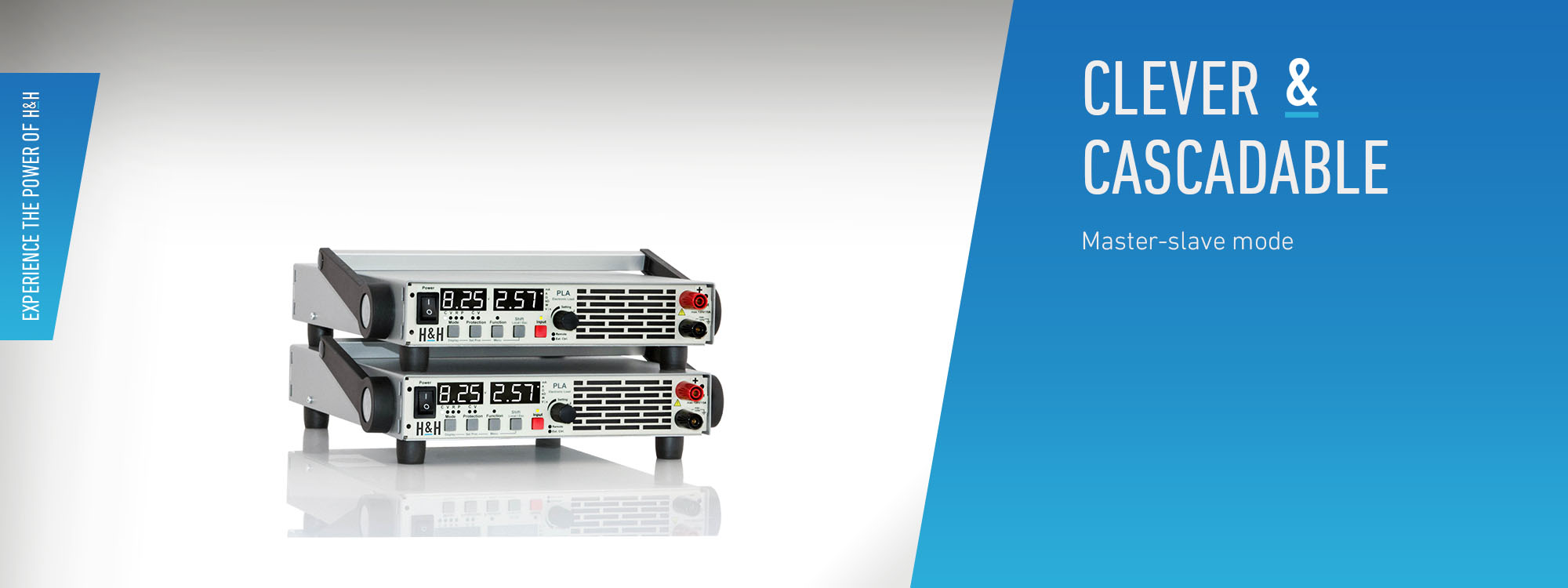
Parallel Connection in Master-Slave Mode
To increase the power or current, electronic loads of the same model can be operated in parallel as one system. For this purpose, the devices are operated in master-slave mode. The master unit controls the entire input current of the system. It also displays the measured values of the system at the user interface and returns them when queried via one of the data interfaces (except CAN). The voltage measured at the master unit is the basis for the regulated settings in voltage, power and resistance mode.
Terminology
System unit
An electronic load is a system unit. It operates in one of the system operating modes Single, Master or Slave. The factory setting for the system operating mode is Single. The system operating mode is not changed during a reset or when power is turned off and on.
System connection
A system connection consists of at least two system units: exactly one master and one or more slave units.
Single mode
In single mode, the electronic load is not connected to any other units via the CAN interface or the I/O port. The entire device functionality and all data interfaces are available without restriction.
Master mode
In master mode, the system unit controls one or more system units in slave mode via the CAN interface and the I/O port.
Slave mode
In slave mode the system unit is controlled by the master unit via the CAN interface and the I/O port. Apart from some diagnostic functions, it cannot otherwise be operated.
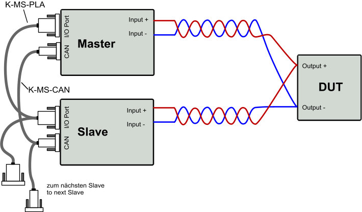
Master-Slave Cable
To create a system connection, we supply the matching cables K-MS-CAN and K-MS-xx (xx = series). In order to be able to continue using the I/O port, e.g. for accessing status signals, the cables can also be assembled by the user himself according to the description in the operating instructions.
Restrictions in System Connection
– Functions for static measurement data acquisition and management are not available.
– The discharge function is not available.
– The V/I characteristic curve function is not available.
– Functions for internal resistance measurement are not available.
– The MPPT function is not available.
– Calibration functions are not available.
– Functions for setting and reading device parameters are only restrictedly available.
– The external CAN interface is not available for communication with a control computer.
– The I/O port is not available when using the master-slave cable K-MS-xx. As a solution for the PLI, ERI, ACL series there is a so-called SubD25 Doubler.
– Communication via a data interface is not possible for slave units. The menu structure of the user interface is reduced to a few diagnostic functions.
– In the master unit, individual functions, menu items of the user interface and SCPI commands are not available or only restrictedly available.