
Features of performance
Details
Model overview
Downloads
- Configurable multi-channel load ⇒ to the
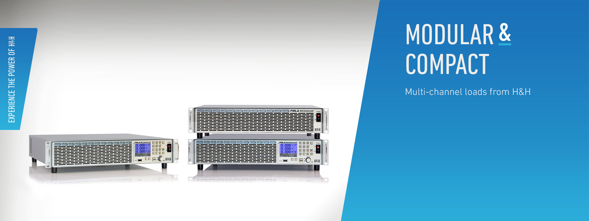
- Up to 12 channels in 19“ , 2 U
- Tailored configurations possible with modules in 4 voltage and 4 power classes
- 150 W - 300 W - 450 W - 600 W modules
- Input voltages 40 V - 60 V - 120 V - 240 V
- Load currents from 1 A to 120 A
- CC - CV - CR - CP mode
- Dynamic loads
- 1,800 W total power
- Operated via graphical user interface with integrated help system
- SCPI programming with measurement function
- Internal measurement data storage
- Electronic protection
- Analog monitoring outputs for voltage and current
- Analog control input
- Extensive data interfaces
- 19 inch mountable
- Channel expansion via Slave devices
- Trigger system
- MPP tracking
- Discharge function
- Watchdog function
- LabVIEW drivers and software tools available for download
- 2 free calibrations

By loading the video, you agree to YouTube's privacy policy.
Learn more
Configuration
The PMLA electronic multi-channel load has up to 3 cooling units, each with 4 mounting positions for load modules. 150 W, 300 W, 450 W or 600 W load modules are available. Depending on power, a module occupies one (150 W), two (300 W), three (450 W) or four (600 W) mounting positions.Load Modules
The modules are available in four different voltages 40 V, 60 V, 120 V and 240 V and currents from 1 A up to 120 A. Various loads can be configured, e.g.: 1 x 600 W + 1 x 450 W + 2 x 300 W + 1 x 150 W The total power is max. 1,800 W. The loads can therefore be easily configured to test units with multiple outputs. The load inputs are galvanically separated. Very simple systems can therefore be specially configured for requirements with multi-channel Burn-In equipment.Operating Modes and Functions
The following operating modes are possible:- Current mode
- Voltage mode
- Resistance mode
- Power mode
- Dynamic mode with up to 100 setting values
Measurement Data Storage
A data acquisition function records up to 100 measurement points (time, voltage, current) at each channel and saves it internally.User Interface
The master device has a graphical user interface. All channels, also those of connected slave devices, can be operated.I/O Port
I/O Port for the following functions.- Load setting C and V
- Load on/off
- Voltage monitor output
- Current monitor output
- Sense inputs
Calibration
A free Factory Calibration Certificate (FCC) is supplied with the devices. The calibration process is subject to supervision in accordance with DIN EN ISO 9001. The calibration certificate documents the traceability to national standards to illustrate the physical device in accordance with the international System of Units (SI). Within the 2-year warranty period, we will calibrate a second time free of charge if the respective device (serial number) will have been registrated at H&H.--> Conditions for a second free calibration
For use under laboratory conditions, H&H recommends a calibration interval of 2 years. This is an empirical value that can be used as a guide for the first period of use. Depending on the intended use, service life, relevance of the application and ambient conditions, the operator should adjust this interval accordinglySoftware Tools und Drivers
LabVIEW drivers and software tools are available for download free of charge.Applications
- Calibration of driver outputs
- Consumer test of electrical systems
Test of:
- Batteries and accumulators
- Cables
- Absorbers
- DC/DC converters
- Electronic assemblies
- Electronic fuses and cut-off
- Fuse boxes
- ECUs
- Power distributors