

An electronic load is the counterpart of a current source, i.e. a current sink. It is a device originally used as an intelligent replacement for a conventional (resistive) load resistor. Today, an electronic load replicates all imaginable types of loads.
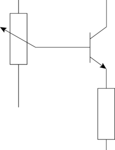
Whereas when loading a voltage source with a fixed resistor, one always sets a specific load current with a single resistor value. The special feature of the electronic load is that it can vary the load current within a defined range. It regulates the current electronically by means of transistors.
Customers use electronic loads in a wide variety of applications, especially for testing power supply and control units, batteries, fuel and solar cells, generators, transformers, uninterruptible power supplies (UPS), on-board power systems and many more.
In addition, H&H electronic loads have a considerable range of functions, which ensure convenient use. With functions such as MPP tracking, discharge function or internal resistance measurement, the devices perform complex processes for measurement and data storage automatically.
Analog and digital interfaces are essential for automated test stands, which electronic loads from Höcherl & Hackl usually provide as standard.
H&H electronic DC loads are used in the automotive, aerospace, railroad, renewable energy, R&D, medical and military industries. DC loads are used to test the following components:
Power supplies, laboratory power supplies
Static or dynamic loading in various modes, burn-in test. To determine the V/I characteristics of power supplies from open circuit to short circuit, one also needs electronic loads that can regulate high load currents at input voltages close to 0V. For this purpose there are special models of DC loads: PLI ZV series.
Control units
When testing control units, simultaneous loading of several different units is often required by simulating different loads, e.g. in a car. We serve such applications with our modular multi-channel load series PMLA, effectively many electronic DC loads in one housing.
Power distribution, cable trees, fuse boxes
Here, too, many different loads are simulated by several channels of a PMLA multi-channel load.
Batteries and accumulators
Energy storage devices are discharged continuously or with defined load profiles to assess their quality. With the discharge function this is done professionally including protection functions and individual shutdown criteria. To cycle accumulators, devices for charging and discharging are necessary. For this purpose, either a power supply can be added to the system in addition to the electronic load, or a source-sink from H&H, which switches seamlessly between charging and discharging mode. The source-sink is available as a 2- or 4-quadrant power supply.
Fuel cells
The PLI ZV zero-volt models are also used for testing fuel cells, because here one has to deal with voltages far below 1 V at high currents. Impedance spectroscopy is used to examine fuel cells in order to determine, for example, the series resistance or the end of life (EOL). The SCL series is designed even more for high currents down to 0 V.
Solar and photovoltaic panels
For PV panels, the maximum power point (MPP) plays a key role. Our DC loads offer the MPP tracking function either standard or optional, depending on the series. For applications with high demands on the accuracy of current control over wide ranges, we have models with several adjustable current setting ranges in our portfolio: series PLI MR.
Testing and simulating components
such as diodes, rectifiers, fuses …
Testing of continuous, short-time or pulsed current capability of active and passive components. With the V/I-characteristic function of the PLA series, the characteristic curve of a component is reproduced in the electronic load. For this purpose, the load sets the corresponding load current depending on the applied input voltage.
Electronic AC loads are used in these areas:
- Testing AC power supplies
- Testing transformers
- Testing inverters
- Testing uninterruptible power supplies (UPS)
- Testing aircraft electrical systems
- Testing generators
- Burn-in test
- Testing smart grids, micro grids / stand-alone grids
- Testing chargers, charging stations, wallboxes
- Testing energy meters
- Testing emergency generators
- Testing according to standards, safety tests
For testing three-phase power supplies, there are the three-phase loads of the ACLT series.
CC, CP, CR, CV are the 4 basic operating modes of almost every H&H electronic load:
- Constant current (CC) operation: Independent of the applied input voltage, the load controls a constant current flow with the current setting value.
- Constant power operation (CP): Depending on the input voltage, the load regulates the current flow so that the power set remains constant.
- Constant resistance (CR) operation: Depending on the input voltage, the load regulates the current flow so that the set resistance remains constant.
- Constant voltage (CV) operation: In voltage mode, the load regulates the input voltage to the specified set point. This is done by adjusting the load current until the desired voltage is established by the DUT’s internal resistance or current limit.
QL series source sinks also have these 4 basic modes of operation.
Combined operating modes are characterized as the interaction of basic operating mode (CC, CR, CP, CV) and adjustable overcurrent or undervoltage protection.
The following combined operating modes are available, depending on whether only one of the limitations is active or both simultaneously:
- CC+CV Constant current operation with undervoltage protection
- CR+CC Constant resistance operation with overcurrent protection
- CR+CV constant resistance operation with undervoltage protection
- CR+CC+CV Constant resistance operation with overcurrent and undervoltage protection
- CP+CC Constant power operation with overcurrent protection
- CP+CV Constant power operation with undervoltage protection
- CP+CC+CV Constant power operation with overcurrent and undervoltage protection
- CV+CC Constant voltage operation with overcurrent protection
The minimum input voltage is necessary at the load input in order to absorb the maximum load current Imax. We specify this minimum input voltage Vmin for each device model in the technical data. The electronic load can regulate lower currents than Imax even at voltages below Vmin.
We use the term source-sink for 4-quadrant power supplies – these are devices that allow both current and voltages in both positive and negative directions.
A 2-quadrant power supply is also a source-sink. Another term for these devices is bi-directional power supply because current can flow both out of the device (source) and into the device (sink). The QL series offers 2- and 4-quadrant models in a wide range of power and with many features.
The sense lines are used to compensate for voltage drops on the load lines.
The longer the load lines and thus the greater the ohmic resistance of the load lines, the higher the voltage drop on them. The greater the difference between the voltage at the output of the device under test (DUT) and the voltage at the load input, the less accurate the control response of the load. To compensate for the voltage drop, connect the sense lines separately and apart from the load lines directly to the DUT output:
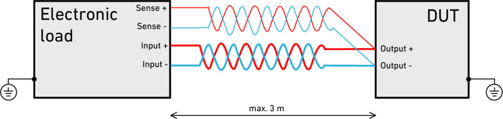
Input and sense lines
If the sense connections are not wired, the load will automatically measure the voltage at the load input. However, the accuracies for voltage measurement given in the technical data only apply when sense lines are connected.
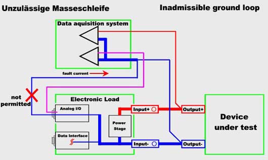
Ground Loops can be prevented by using galvanically isolated analog inputs at the data acquisition system or electronic load. For this case we can offer a “galvanically isolated analog I/O port for many series”. The standard analog I/O card can be exchanged by an insulated version. All measuring and controlling signals are connected via insulating amplifiers and optocouplers.
Each electronic load has a certain input capacity (see technical data). This is hardly noticeable with clean DC input voltages.
However, if the voltage at the load input is superimposed with an AC voltage component, the load current also contains an AC current component depending on the amplitude and frequency of the AC voltage. This is not an oscillation of the electronic load.
If the amplitude portion or the frequency of the AC voltage component is high, an overload of the input capacity can occur!
The accuracy values given in the technical data apply for clean DC voltages at the load input.