
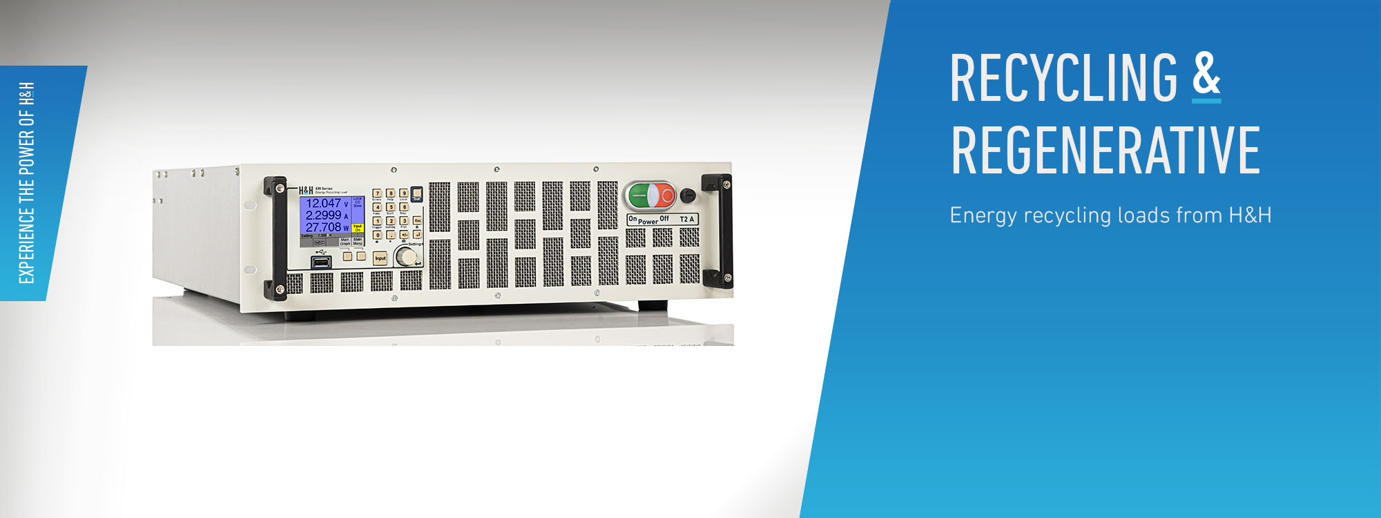
ERI Series - Regenerative
Features of performance
Details
Model overview
Downloads
End of Life ERI Series: Oct. 31, 2023
- Input voltage up to 400 V
- Load current up to 220 A
- Power up to 10.8 kW
- Energy recycling to the local power grid
- Low heat waste, silent, lab operation
- Basic operating modes CC - CV - CR - CP
- Combined operating modes CC+CV, CR+CC+CV, CP+CC+CV, CV+CC
- Ethernet + USB + RS-232 + CAN as standard
- GPIB optional
- Intuitive operation
- Fast operation by shortcuts
- Settings toggling
- MPP tracking
- Energy storage test
- Internal resistance measurement
- SCPI programming with measurement function
- Dynamic loads with synchronized DAQ
- Trigger model
- Data storage directly to USB mass storage device
- Adjustable protections for undervoltage and overcurrent
- Galvanically isolated fast I/O port optional (analog control input, analog monitor outputs for voltage and current, digital input and programmable output)
- Digital Master-Slave operation
- Settings saving
- Electronic protection
- Bilingual help system (German, English)
- 2 free calibrations (with registration)
End of Life ERI Series: Oct. 31, 2023
Description
ERI Series electronic loads feed the consumed energy back to the local power grid. Another feature of these devices is an extensive variety of standard data interfaces. Apart from Ethernet, USB and RS-232 there is a standard CAN interface. GPIB can be installed as an option (ERI02). Programming is done in SCPI with an extensive command syntax.Cooling
ERI loads recover the consumed energy instead of converting to thermal energy. Thus, electricity costs are reduced and the environment is only slightly warmed. As a consequence, in many cases air-condition is unnecessary. Energy recycling loads do not need powerful fans. That makes the devices acceptably quiet and therefore perfectly fit for laboratory operation.Energy Recycling
The consumed energy is fed back to the mains supply with an efficiency of ca. 90 %. The operation in the sense of a power generation into the public electricity grid is not provided with these energy recycling loads. The load must be connected to a low-voltage mains supply with a fixed installed and separately fused supply line. The ERI load has a simple and non-redundant monitoring of the power supply. If limit values are exceeded, it switches off the power stage unit. This monitoring does not replace any grid or system protection which must be installed if necessary for the protection of persons and the local grid.Operating Modes and Functions
Basic and Combined Operating Modes
The devices have the operating modes constant current (CC), constant voltage (CV), constant resistance (CR) and constant power (CP). Furthermore, protection values for undervoltage and overcurrent can be set in each operating mode. This results in the combined operating modes CC+CV, CR+CC+CV, CP+CC+CV, CV+CC.Dynamic Load with List Function
Dynamic operation (LIST function) can be configured by up to 300 list point settings. The electronic load saves the synchronously acquired measurement data with timestamp.Data Acquisition
An automatic data acquisition function allows to store measurement data internal or directly on an external USB flash drive.Energy Storage Test/Discharge Function
The discharge function discharges energy storage devices such as accumulators, batteries, ultracaps etc. in a controlled manner under definable switch-off conditions. The values determined in the process, such as charge and energy, can be read locally and via a data interface.Internal Resistance Measurement
The electronic load can measure the DC internal resistance of the connected test object. For this purpose it uses a calculation method which is specified in various standards, e.g. DIN EN 61951, DIN EN 61960.Watchdog Function
If the watchdog function is activated, the load input is switched off in case of faulty communication with the control PC in order to protect the connected DUT.MPP Tracking (option ERI21)
The Maximum Power Point Tracking (MPPT) function is used to test solar or photovoltaic modules. For this purpose the maximum power point (MPP) of the connected DUT is controlled in CV mode.Trigger Model
A configurable trigger model controls data acquisition, static and dynamic settings.Parallel Connection in Master-Slave operation
To increase the power or current capability electronic loads of equal model can be operated in parallel in Master-Slave mode as one system. ERI series loads need the optional I/O port (ERI06) for this purpose.Loading Capacity
The model range covers power classes from 600 W, up to 28,000 W continuous power rating. In addition the models up to 300 V have an overload capability. The height and duration of the possible overload depends on the temperature of the power stage. The unit indicates the currently possible overload. Therefore the units can be used even for considerably more powerful applications.Protections
- Current limitation
- Power limitation
- Overtemperature protection
- Simple mains supply monitoring
Data Interfaces
The following data interfaces are included as standard:- Ethernet
- USB
- RS-232
- CAN
- GPIB (option ERI02)
Galvanically Isolated Fast I/O Port (Option ERI06)
Optional galvanically isolated I/O port to prevent ground loops, for following functions:- Load setting C and V
- Analog setting of C and V protections
- Load on-off
- Operating mode selection
- Voltage monitor output
- Current monitor output
- Trigger input
- Trigger output
- Digital input
- Programmable digital output
Calibration
A free Factory Calibration Certificate (FCC) is supplied with the devices. The calibration process is subject to supervision in accordance with DIN EN ISO 9001. The calibration certificate documents the traceability to national standards to illustrate the physical device in accordance with the international System of Units (SI). Within the 2-year warranty period, we will calibrate a second time free of charge if the respective device (serial number) will have been registrated at H&H.--> Conditions for a second free calibration
For use under laboratory conditions, H&H recommends a calibration interval of 2 years. This is an empirical value that can be used as a guide for the first period of use. Depending on the intended use, service life, relevance of the application and ambient conditions, the operator should adjust this interval accordingly.Documentation
Each electronic load is supplied with a user manual as PDF file and printed General Safety Instructions, each in German and English.Manuals
Software/Drivers
Load_Control_1.0.0.zip
Software Tool for control of PLI (up from FW 4.3.0), PLI-MR (up from FW 1.0.0), ERI (up from FW 2.0.0), TRL (up from FW 1.0.0) and SCL (up from FW 1.0.0) loads.
Software Tool for control of PLI (up from FW 4.3.0), PLI-MR (up from FW 1.0.0), ERI (up from FW 2.0.0), TRL (up from FW 1.0.0) and SCL (up from FW 1.0.0) loads.
LoadTerminal_1.1.0.zip
Software tool for transmission of single commands via GPIB/RS-232/Ethernet/CAN
Software tool for transmission of single commands via GPIB/RS-232/Ethernet/CAN