
SCL Series - High Current
Features of performance
Details
Model overview
Downloads
- Voltage 12 V or 40 V
- Currents up to 1,200 A
- Loading down to min 0.6 V or even to 0 V (SCL ZV) at maximum current
- User interface with 4.3" touch screen
- Basic operating modes CC, CV, CP, CR
- Combined operating modes CC+CV, CR+CC+CV, CP+CC+CV, CV+CC
- Adjustable protections for V and I
- Functions for testing energy storage devices
- Internal resistance measurement
- Master-slave operation for parallel connection
- V/I characteristics sweeping
- List function with synchronous data acquisition
- Rectangular, PWM and modulation function
- MPP tracking
- Trigger model
- SCPI programming with measurement functions
- RS-232, USB, LAN, CAN, I/O port standard
- GPIB optional
- I/O port as standard
- Isolated I/O port optional
- Analog monitoring outputs for voltage and current
- Analog control inputs for control V/I and limit V/I
- Save settings
- Electronic protection
- Bilingual help system (DE, EN)
- 2 free calibrations (with registration)
Description
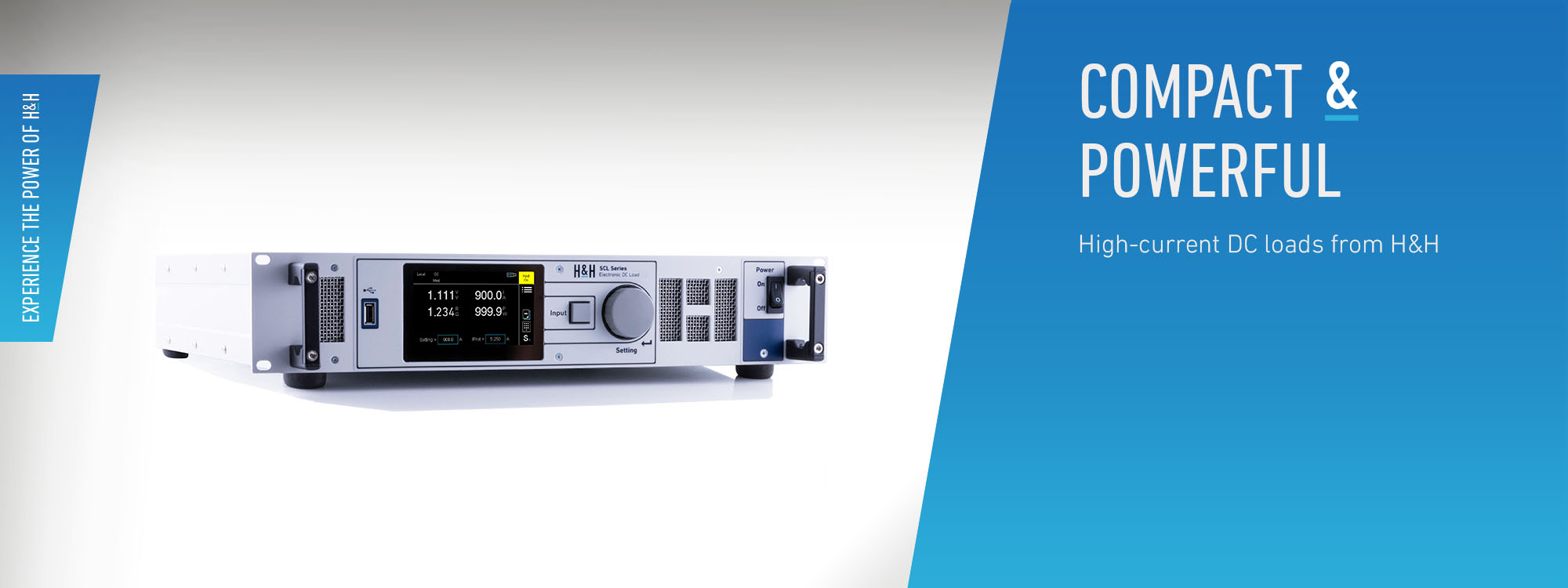
Electronic loads of the SCL series already load the connected source from 600 mV with maximum load current of up to 1,200 A, the SCL ZV variant even from 0 V. They are therefore ideal for test objects such as fuel cells and other high-current voltage sources. In the compact 19" housing with only 2 U, there are models with different power classes.Operating Modes
Basic Operating Modes
The devices have constant current (CC), constant voltage (CV), constant resistance (CR) and constant power (CP) operating modes.Combined Operating Modes
In the basic operating modes, a protection value for undervoltage and overcurrent can be set. This allows the combined operating modes CC+CV, CR+CC+CV, CP+CC+CV, CV+CC to be realized.Functions
List Function
In all operating modes CC, CV, CR, CP the electronic loads can produce load profiles by List function. Up to 300 settings with variable dwell and ramp times are possible. Sample times can be defined for each section separately. The electronic load synchronously measures voltage and current and saves the data with timestamp.Rectangular Function
The rectangular function provides a convenient way to generate a rectangular waveform by entering absolute time and amplitude values.PWM Function
With the PWM function, the switching frequency and the duty cycle can be set for the two amplitude values in manual operation.Modulator
The modulator adds a sinusoidal, square-wave or triangular signal to a static setting in CC or CV mode. Frequency and modulation depth are adjustable.Sweep Function
To determine V/I characteristics, a voltage ramp by means of start and end voltage and the corresponding duration of the sweep process is defined. The ramp can be rising or falling. During the execution of the sweep process, the measurement data is recorded. The electronic load adjusts the sampling time so that a maximum of 360 measurement points are recorded. After the function has been executed, the recorded measurement data can be viewed in the graphical "Data Viewer" or exported to a connected USB flash drive.MPP Tracking
The Maximum Power Point Tracking (MPPT) function consists of the two sub-functions Sweeping and Tracking, which alternate continuously in an adjustable interval. If the measured open circuit voltage at startup is higher than the minimum voltage, the electronic load performs a sweep and then adjusts the global MPP found. The swept V/I curve is displayed together with the V/P curve in the function graph of the user interface. The currently determined MPP is marked by a '+' in the diagram. The V/I characteristic can be read via a data interface.Energy Storage Test: Discharge Function
The discharge function tests energy storage devices such as batteries, ultracaps and electrolytic capacitors etc. by discharging them in CC, CP or CR mode. The discharge function can be combined with the list function so that pulsed discharge is possible. IUa discharge (CC+CV discharge) is also possible: the test object is discharged with constant current up to a defined voltage. This voltage is then kept constant until a defined minimum current is reached. Stop criteria are charge, energy, time, current, voltage. During data logging, a follow-up time can be defined to observe the regeneration phase.Internal Resistance Measurement
The electronic load can measure the DC internal resistance of the connected source. For this purpose, it uses a calculation method specified in various standards, e.g. DIN EN 61951, DIN EN 61960.Measurement Data Acquisition
Automatic data acquisition allows measurement data to be stored internally or directly to an external USB flash drive.Trigger Model
Various functions or settings can be triggered by a configurable trigger event:- Activate/deactivate load input
- Start/stop LIST function
- Start/stop data acquisition
- Set triggered settings of all operating modes
Available trigger sources:
- External
- Bus
- Manual
- Voltage
- Current
Control Speed Selection
For certain DUTs or very long cables, it may be necessary to adjust the eload's regulation time constant to avoid oscillation and to achieve stable operation. The control speed can be selected from slow - medium - fast.Watchdog Function
When the watchdog function is activated, the output is switched off in the event of faulty communication with the control PC in order to protect the connected DUT.Master-Slave Operation
To increase the power or current, up to 5 equal devices can be operated in parallel in a master-slave connection. The system behaves in the network externally like one single device. The master unit controls the total current of the system, displays the total measured values and supplies these when queried via one of the data interfaces. Cabling: One set each of K-MS-SCL and K-MS-CAN master-slave cables on all slave units (to be purchased from H&H or assembled by the user). To be able to tap monitor signals etc. when using the master-slave cable K-MS-SCL, we offer a SubD25 coupler as an accessory.Saving Settings
In order to be able to quickly reconstruct recurring test tasks, the active settings can be stored in non-volatile memory (internally or on USB flash drive) so that they can be reloaded at a later time. 9 internal memory positions are available. The unit can selectively set reset values at power-up, the last active settings at power-down, or memory positions 1 to 9.Data Interfaces
The following data interfaces are fitted as standard:- Ethernet
- USB
- RS-232
- CAN
Optionally available:
- GPIB Interface (option SCL02)
I/O Port
The standard I/O port provides analog and digital signals for external control.Inputs:
- Analog setting of I and V with 0 ... 5 V or with 0 ... 10 V
- Analog protection setting of I or V with 0 ... 10 V
- Load activation
- Operating mode selection CC/CV
- Control speed selection
- Remote shut-down
- Readable digital input
- Trigger input
Outputs:
- Analog voltage monitoring output 0 ... 10 V
- Analog current monitoring output 0 ... 10 V
- Load input activation status
- Overload status
- Programmable logic output
- Trigger output
Galvanically Isolated I/O Port
For galvanic isolation of the I/O port from the output circuit and thus to prevent ground loops, the option SCL06 can be installed. The galvanically isolated version is pin compatible to the standard version.Help System
The integrated help system supports the user in the manual operation of the devices. The language can be switched between German and English.Calibration
A free Factory Calibration Certificate (FCC) is supplied with the devices. The calibration process is subject to supervision in accordance with DIN EN ISO 9001. The calibration certificate documents the traceability to national standards to illustrate the physical device in accordance with the international System of Units (SI). Within the 2-year warranty period, we will calibrate a second time free of charge if the respective device (serial number) will have been registrated at H&H.--> Conditions for a second free calibration
For use under laboratory conditions, H&H recommends a calibration interval of 2 years. This is an empirical value that can be used as a guide for the first period of use. Depending on the intended use, service life, relevance of the application and ambient conditions, the operator should adjust this interval accordingly.Documentation
We supply a user manual as pdf file and printed General Safety Instructions, each in German and English.Software/Drivers
Load_Control_1.0.0.zip
Software Tool for control of PLI (up from FW 4.3.0), PLI-MR (up from FW 1.0.0), ERI (up from FW 2.0.0), TRL (up from FW 1.0.0) and SCL (up from FW 1.0.0) loads.
Software Tool for control of PLI (up from FW 4.3.0), PLI-MR (up from FW 1.0.0), ERI (up from FW 2.0.0), TRL (up from FW 1.0.0) and SCL (up from FW 1.0.0) loads.